Gravity Dynamics and Gravity Noise on the Earth Surface
Measuring device description
Libor Neumann
Prague
October 2004
Content
The adjustable microcamera holder
Software installation basic steps
Additional modules installation
Condition preparation for measure and focus programs
Installation and adjusting procedure
The fixed microcamera holder fastening
The weight suspending and adjusting
The microcamera fastening and adjusting
The microraster placement and adjusting
Measurement end and connected measurement start
Introduction
The appendix goal is detail description of measurement device.
The description can be used for independent measurement replication or for more detailed study of measurement device features.
The appendix contains description of all measurement device parts in separate chapters, description of software installation basic steps, assembling procedure description, description of installation and adjusting procedure and measurement process description.
Global description
Measuring device was designed to measure time dependency of gravity field gradient variation. Primary design goals are a minimal complexity of device, small number of parts and a simplicity and accessibility of all parts. The goals are caused by need of:
- Minimal systematic errors
- Obtaining qualitative reliable results with acceptable precision of quantitative values
- Enable building and running of measurement device in real conditions
- Enable independent reproduction of measurement in real conditions
Basic physical principle of gravity field gradient actual value measurement is the weight fastened to a fixed hanger. Suspension direction time dependence gives time dependence of gravity field gradient.
Weight fastened to fixed hanger works like a pendulum. Every force impulse forcing the weight changes movement of the weight. The time dependency of suspension direction is superposition of gravity field gradient change and pendulum movement.
Pendulum movement measurement is out of experiment goals. The pendulum movement should be eliminated directly in measurement device design by use of absorber. The absorber decreases pendulum own resonance oscillation quality. The pendulum oscillation is still present in measurement results; the amplitude is decreased by the absorber.
Measurement interval is 15 – 60 s. The own pendulum oscillation period is about 3 s. The weight torsion oscillation period is about 20s. Results used for analysis are namely 30min average or in some cases 3 min averages. The own pendulum oscillations are included in measurement result as a noise and the absorber radically decreases the noise level.
Gravity field gradient direction change can be gauged either as force value change in horizontal plane or as weight position change (i.e. suspension direction change).
The first measurement device generation was based on measurement of force value change in one direction in horizontal plane (strain gauge was used). The second generation measurement device described in this appendix measures the gravity field gradient change as the weight position change in horizontal plane (two dimension measurement).
Several physical principles can be used in
the measuring device design. Following physical principles was considered:
- Electromagnetic position measurement in two axes
- Capacity position measurement by several sensors
- Distance measurement by laser distance meters in two axes
- Optical position measurement in plane
Optical position measurement in plane principle was chosen in measurement device design. The decision was based on following reasons:
- Any force interaction of measurement sensor with the weight is eliminated in principle. Optical measurement is generally supposed to be without force interaction. Only very weak light force interaction is known in the light beam direction. In this case light beam direction is orthogonal to measurement plane.
- Measurement can be made by one sensor in two dimensions simultaneously. Errors caused by different sensors like different work conditions, different sensor orientation, and different sensor parameters or interactions between sensors are eliminated in principle.
Mechanical design of measuring device is as simple as possible. No high technology is used, no high precision tool and no special technological process was used.
Every mechanical element was designed to enable manufacturing in common conditions and to enable adjusting of measuring device in different conditions and long term run of measuring device.
It was refused adding of special construction enhancements to increase measurement sensitivity or precision.
Any element dimension or other parameter has no basic physical meaning. The element dimensions and other parameters were chosen with respect of manufacturing in real conditions. Only the very basic parameters have physical meaning, like used materials, symmetry and basic dimension relations.
Mechanical elements
All mechanical elements of the measuring device are described in this chapter.
The weight
The weight is made from electromagnetically neutral material. No insulator material was used to prevent electrostatic forces. No high conductivity material was used to prevent electromagnetic induction and secondary magnetic force caused by inducted currents.
The weight is cylindrically symmetric with vertical symmetry axis. It respects circular symmetry in measuring plane. Spherical symmetry is not needed and spherically symmetric weight should be more complicated to manufacture and other parts of measuring device should be more complicated.
The weight orientation in measurement plane is irrelevant with respect of cylindrically symmetry.
The weight was made from concrete. Ceramic porous form was used for concrete shaping. The form is part of the weight. The weight mass is approximately 5 kg.
Approximate dimensions and shape of the weight are on the following figure. The dimensions and shape are dependent on easy available parts.
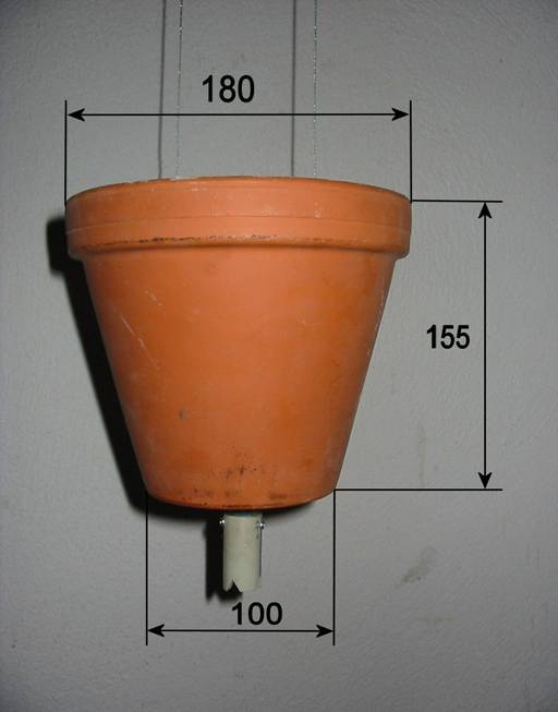
Figure 1 - The weight - all dimensions are in mm
The hanging wire is fixed the way to enable placing the microraster and the microcamera in the weight symmetry axis.
The hanging wire fixture cancels the weight cylindrical symmetry and defines two possible orientations of the weight with respect of camera holder. The both orientations are equivalent and they are not distinguished each other in measurement.
The hanging wire
The hanging wire is used to fix the weight to the weight holder. The material with sufficient length stability and sufficient flexibility was chosen.
The long time maximal length stability and long time torsion stability are the main parameters for material selection. One measurement continues from weeks to months.
The length change in range of tenths of mm causes snapped image defocusing. Torsion change rotates the weight and the microraster. It causes measurement errors connected with nonzero distance between the microcamera vertical axis and the weight vertical axis. It can cause systematic measurement errors if the torsion angle change is great.
Ideal hanging material was not accessible. Steel wire was selected as acceptable compromise. The wire with much greater loading capacity than the weight mass was used to minimize length ageing. The wire with acceptable flexibility is in contradiction with this. The steel cable wire with diameter of 1 mm or 1.4 mm was used.
The hanging wire construction was used to enable using only one piece of the wire and enable placement of the microraster and the microcamera in vertical weight and suspension axis.
Common electrician clip was used to fix the wire position and the spacer position. The spacer was made from aluminium hollow bar.
The hanging wire construction and fixing to the weight is shown on following figure.
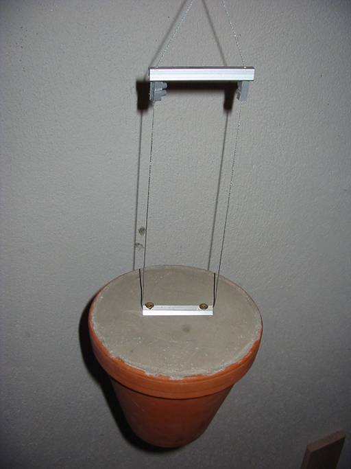
Figure 2 - Fixing the hanging wire to the weight
The absorber
The absorber is designed to add loss into pendulum dynamic system and decrease pendulum resonance quality. The absorber design decreases all pendulum periodic movement, both in horizontal plane and torsion swing.
The absorber is cylindrically symmetric. It is placed in the weight symmetry axis.
The absorber consists from:
- Fixed small container
- Movable ring
- Liquid filling
Fixed small container is placed on solid background. It is not specially fixed.
The container is filled by mineral engine oil. The container capacity is approximately 10 cm3.
The ring is fixed to the weight to enable vertical adjusting. The ring contains several snicks to prevent torsion swing.
The movable ring is inserted into container with liquid filling. Ring vertical position is adjusted to be plunged into liquid filling and do not touch container bottom.
The container is adjusted to place ring symmetrically relatively to the container.
The container and the ring are made from easy available materials. Polyethylene parts were used.
Liquid filling is easy available mineral engine oil. It was selected due to its long term stability and minimal vaporization. The oil viscosity is acceptable.
The measuring device is not sensitive to absorbing parameters of the absorber and their change. The absorber parameter change causes only resonance quality change. The resonance quality change affects only measured result noise amplitude.
The container size is minimal in common manufacturing conditions. The minimal capacity should minimize side effects of liquid filling to the weight like liquid flow effect.
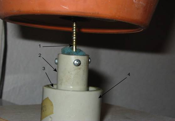
Figure 3 - The absorber; 1- vertical adjusting rod, 2- movable ring, 3 - oil filling, 4 - fixed container
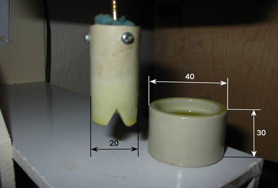
Figure 4 - Disassembled absorber with basic dimensions in mm
The microraster holder
The microraster holder is used to fix the microraster right position to the weight and microcamera. It is used for fine adjusting of microraster vertical position with respect to the weight and microcamera, for adjusting horizontal microraster plane tilt and to fix the position of microraster relative to the weight.
The microraster is fixed to the microraster holder by two elastic strips before the microraster holder is placed on the weight. The microraster holder must be placed the way to fix the microraster in microcamera vertical axis between the microcamera objective and light source.
Three screws are used for the fine microraster vertical position adjusting in centre of focusing range of microcamera and for adjusting horizontal plane tilt. The microraster plane tilt is the same as microraster horizontal plane. The screws fix the microraster holder position relative to the weight. Water level indicators are placed orthogonally to enable independent indicating of horizontal plane. The adjusting screws create right-angled triangle to enable independent adjusting of horizontal plane.
The microraster holder base is made from plexiglass to enable microraster lighting. Screw holders are heat fastened to plexiglass.
The holder base dimensions are not critical. They are adapted to dimensions of other components, namely the water level indicators ones.
The holder is not specially fixed to the weight. It is placed on the upper site of the weight.
The holder is designed not to touch with any other measuring device parts. Only screw ends are in touch with the weight. Every gap between the holder and other measuring device parts should be minimally 2-3mm (except the gap between the microraster and the microcamera lens).
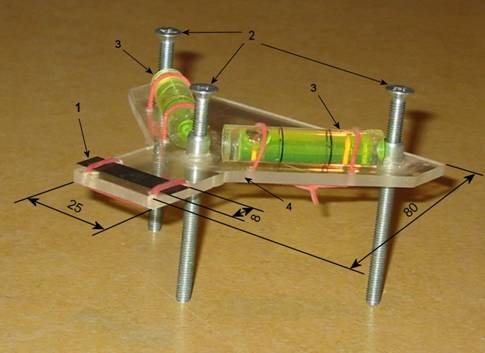
Figure 5 - The microraster holder; 1- microraster, 2-adjusting screws, 3-water level indicators, 4-holder base
The microraster
The microraster is made from microfiche. Technological testing microfiche was used for microraster. One part of one row of “pages” sized approximately 30x8mm was used. The part of the microfiche was placed into the microraster holder so the “page” used for measurement is placed in the holder central axis. The rest of the strip is not optically snapped, it is used only to fix the microraster to the holder.
Many different materials were tested in design phase of the measuring device to be used as the microraster. The testing results show unsuitability of materials with repetitive regular pattern, with great number of very small patterns or with very great patterns. The optimal microraster should contain medium size patterns (about 8-20 patterns in the microcamera visual field) with different shapes (like different letters). Great advantage is use of asymmetrical patterns with very different and simple boundary and very contrast pattern. It is not advantageous to use patterns with small details or patterns with many grey levels.
During the measurement process the microraster image is unfocused (by the measuring device parts ageing, by temperature change and by the hanging wire temperature dependence, by the building small movements). The microcamera image sharpness area is not very great. It is the reason why many pattern details disappear and grey levels are changing. In the same time the weight moves and the microraster with patterns changes the position. Only horizontal position change should be measured.
The measuring algorithm will be more reliable if pattern boundary in the microcamera visual field can not be interchanged each other.
Selections of the microraster and the patterns have great influence to the reliability of the measured results.
The measurement raw results contain indicators to enable evaluating of measurement reliability, namely pattern interchange probability. The results contain number of significant parametric transformation results, their weights and positions. The greater number of the significant parametric transformation result and the higher weight of the results, the greater risk of wrong position evaluation caused by pattern interchange [4].
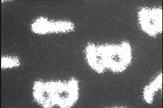
Figure 6 - Focused snapped microraster image example
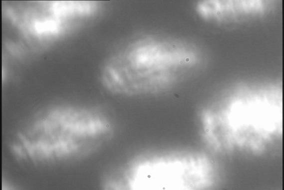
Figure 7 - Unfocused snapped microraster image example
The weight holder
The weight holder is used to fix the weight to the building ceiling. The holder is fixed by two screws to the solid part of the ceiling. The holder is used to the rough weight vertical position adjusting and for the weight orientation adjusting.
The holder is made from steel sheet. The holder loading capacity is many times greater than the weight mass (approximately several hundreds of kg). The holder oversizing minimizes deformation and ageing.
The lock is made from brass tube with two screws. Internal part of common electrician clip is used.
The weight vertical position is adjusted by the lock shift on the hanging wire.
The weight orientation is adjusted by the lock turn. The lock should be turn to the position excluding touching of any part of the weight or the hanging wire with other parts of measuring device. The position should respect the possibility of small weight orientation change during the measurement process caused by temperature dependency and by material ageing.
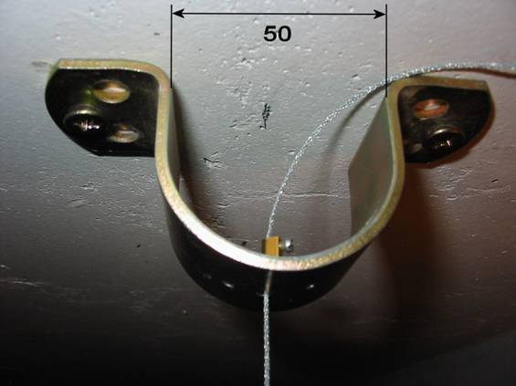
Figure 8 - The weight holder
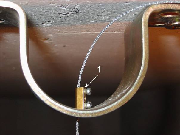
Figure 9 - The weight holder detail; 1-lock
The fixed microcamera holder
The fixed microcamera holder is designed to fasten the microcamera to the building in area of the weight. The holder is made from oversized angle iron and from carrying board.
The angle iron loading capacity is many times greater than the microcamera mass to prevent deformation. The carrying board is made from solid, flat, moisture-proof material (texgumoid was used). Fixing beams are attached to the carrying board by screws. The fixing beams are used to adjust and fix the adjustable microcamera holder to the fixed microcamera holder.
The adjustable microcamera holder position is adjusted by shifting of the adjustable holder in horizontal plane and final position is fixed by screw tighten. It is possible to adjust microcamera position in horizontal plane in range of a few cm and it is possible to slightly adjust orientation of microcamera relative to the building walls.
The fixed microcamera holder is fastened to the solid part of the wall by one or two screws.
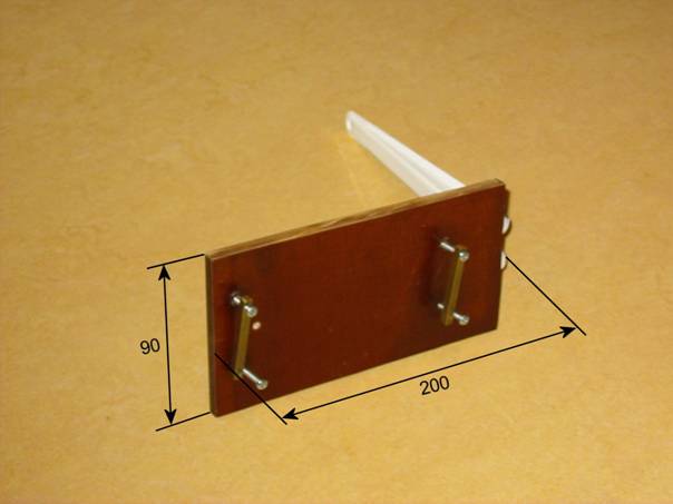
Figure 10 - The fixed microcamera holder
The adjustable microcamera holder
The adjustable microcamera holder is used for:
- fastening the microcamera to the fixed microcamera holder in the right place in horizontal plane,
- focusing image by fine vertical move of the microcamera,
- holding illuminating LED,
- connecting electric signals cables (power and video signal).
The adjustable holder is made from duralumin hollow beams. The material was selected due to its accessibility and easy handling. Focus arm is fastened by small hinge. Focus screw is completed by spiral spring to fasten the arm in stable position.
Focus screw turning rise or descend the longer part of the focus arm. The smaller part moves the microcamera.
The microcamera changes its optical axis by this focusing. The optical axis change is maximally 3° in the whole focusing range and is stable during whole measurement experiment. The optical axis error causes different focus in different parts of the snapped image. The error is not significant. The defocusing during experiment caused by other effects can be many times greater and time dependent. The defocusing is eliminated by image processing algorithm.
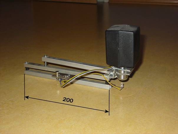
Figure 11 - The adjustable microcamera holder with covered microcamera
The microcamera
The microcamera consists from microscope objective, objective extension and CCD TV camera.
The microscope objective contains main part of the microcamera mass. The completed microcamera is fastened to the adjustable microcamera holder by microscope objective. The objective direct fixing to the holder eliminates errors caused by other parts deformations and instability. It minimizes mechanical strain of the microcamera. The objective stable position is very important for measurement.
Microscope objective with amplification 50-60x was used.
Objective extension length is adapted to the objective optical features. Total microcamera amplification in the range of approximately 1:2 is possible to change by the objective extension length modification. Exact optical amplification value is not a critical measurement parameter. Only time stability of the amplification is important.
The time stability is based on dimension stability of all parts included in optical system. The dimension stability is sufficient for the designed measurement precision. Designed measurement precision is not very high and it is possible to use easy accessible materials and very simple construction.
Objective extension is made from polyethylene pipe. The pipe is fastened to the objective using heat fastening. Standard 1/3” black and white CCD camera without its own objective is fastened to the objective extension by thee small screws. Type MTV-251CM or MK-0320C with 4.8mm x 3.6mm sensor was used.
Microcamera optical system is very simple optical system, it contains only one lens. The only lens is in microscope objective.
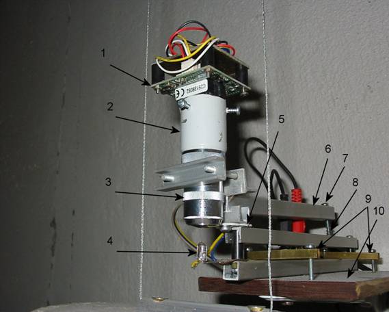
Figure 12 - The uncovered microcamera fastened into adjustable holder and fixed holder; 1- CCD camera without its own objective, 2- objective extender, 3- microscope objective, 4- illuminating LED, 5- small hinge fastening focus arm, 6- focus arm, 7- focus screw, 8- spiral spring, 9- fixing beams, 10- carrying board of the fixed holder
The computer
Standard personal computer (PC) with Intel compatible processor is used. Hardware configuration is standard. Minimal configuration is:
- PC with Intel Pentium compatible processor running minimally at 100MHz
- Minimally 64MB RAM
- HDD minimally 1GB
- Standard keyboard, VGA monitor, standard 10BaseT Ethernet network card
Standard PC is equipped by TV capture card based on chipset Bt848 or Bt878 (type AVer-EZCapture from AVerMedia was used).
Basic software:
- Operating system RedHat Linux V5.2.
- Video card driver Video4Linux bttv-0.6.4
Special software used for measurement:
- Measuring program obrfiltr9 in source code
- Auxiliary focus program snimky1 in source code
- Auxiliary measurement start files init.bmp, init.txt
- Measuring and auxiliary scripts measure, initobrfiltr, focus, ziping
- Configuration and setup files crontab, rc.local, conf.modules
Special software is included in attached files astra.tar.gz or astra.tar.
Software installation basic steps
The basic installation steps are described. The text is not detail installation manual. The right installation procedure can be different with different hardware variant and the equally good result can be reached by other way.
Basic steps describe separate software parts installation.
Basic installation
RedHat Linux V5.2 was used:
- Initial installation from installation CD as workstation – time set as UTC
- Set partition /boot as active (use fdisk – DOS) to enable boot from HDD
Additional modules installation
- Add wu-ftpd-2.4.2 module (ftp demon) by rpm -i
- Add kernel-source-2.0.36 module
- Add zgv-3.0 module
FTP server installation
FTP server is used for measured results transfer. FTP can help in installation process. It is not used for measuring process.
- Add user by linuxconf
- Add hosts in /etc/hosts
Bttv driver installation
Bttv driver serves video card in used Linux version. Different video card model or different Linux version can need other driver or other configuration parameters. Different video card may require modification of source code of measuring and auxiliary programs source code.
Linux core rebuild supporting loadable modules is needed. The core rebuild:
- make config in directory /usr/src/linux-2.0.36 - prompt loadable module support
- make dep
- make clean
- make
bttv installation:
- bttv-0_6_4.tar.gz file copy
- unpack tar -x -z -v -f bttv-0_6_4.tar.gz in working directory (/sw/drivers/)
- source code modification – comment the row with u_int32_t command declaration in bttv.c in bttv/driver directory
- follow INSTALL (change Makefile + make + make ins)
- you can change update script parameters in bttv/driver directory with respect INSTALL description like:
tuner type=4 # no tuner
bttv card=6 # AverMedia
Automatic bttv loading in startup:
- Copy all needed modules (bttv.o, i2c.o, tuner.o, videodev.o) into directory /lib/modules/misc
- Check with modprobe -l
- Create module dependency by depmod bttv.o i2c.o tuner.o videodev.o
- Add parameter configuration in /etc/conf.modules - options, (do not use path, any implicit path is deleted)
- Add into /etc/rc.d/rc.local command modprobe bttv on the beginning and add measurement starting command sh /measure/measure
File content examples.
/etc/conf.modules:
options i2c verbose=1 scan=1 i2c_debug=0
options tuner debug=0 type=4
options bttv radio=0 card=18
/etc/rc.d/rc.local:
#LiNe bttv driver loading
modprobe bttv
#runs measure
sh /measure/measure
Condition preparation for measure and focus programs
Program working with video card needs header videodev.h in directory /usr/include/linux for make:
cp /..../bttv/driver/videodev.h /usr/include/linux
Focus program
Focus program is used as substitutive way to focus snapped image. Primary way should use Linux package kwintv. The kwintv package did not work properly with all used video card type.
Focus program setup:
- Copy files snimky1.c, focus, init.txt, init.bmp into working directory /measure/focus
- Possible modification of source code snimky1.c with respect of used hardware
- Compile and link focus program source code gcc snimky1.c
- Focus program exe rename mv a.out snaps
Measure program
Measuring program measure is installed by compiling source code with modified configuration parameters in source code (like video source, timing parameters, measuring device number in output results):
- Copy files initobrfiltr, measure ,ziping, obrfiltr9.c into working directory /measure
- Source code obrfiltr9.c modification with respect of used video card, PC speed, measuring device identification
- Compile and link gcc obrfiltr9.c
- Measuring program exe rename mv a.out obrfiltr
- Change access right of scripts initobrfiltr, measure, zipping to enable execute
- Create data directory /measure/data
- Copy init files init.bmp and init.txt into /measure/data directory
- Test runs
Crontab configuration
Modification of standard system crontab
- Create crontab for root (by crontab command or cp crontab /var/spool/cron/root)
- Crontab modification:
## result ziping
5 11,23 * * * /measure/ziping >/dev/null
## preventive reboot
25 23 * * 1 /sbin/shutdown -r now
## time synchronization
15 23 * * * /sbin/hwclock --adjust
16 23 * * * /sbin/hwclock --hctosys
System time setup
UTC time zone check – correct link:
lrwxrwxrwx 1 root root 23 listopad 4 01:53 /etc/localtime -> /usr/share/zoneinfo/GMT
file /etc/sysconfig/clock content:
UTC=true
ARC=false
Periodic system time management:
- System time checking date and hwclock --show
- Manual system time setting from external clock hwclock --set a hwclock --hctosys
Automatic PC HW clock adjusting is in crontab.
Real masses
The following table contains real masses of the main parts. The real measuring device was disassembled and the parts were weighted. The results are in the table.
Table 1 – Real masses of the measuring device parts
Measuring device assembling
The following pictures show partially and fully assembled measuring device. They describe relations between parts.
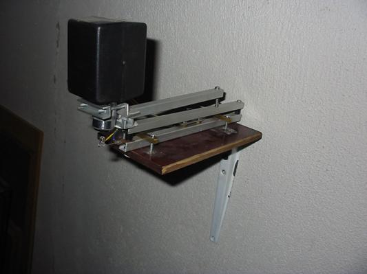
Figure 13 - The assembled microcamera
The assembled microcamera contains the fixed microcamera holder, the adjustable microcamera holder and the covered microcamera.
The assembled microraster holder figure shows adjusted microraster holder with the microraster. The holder is placed on the weight in the right position. The adjustable microcamera holder with the microcamera is disassembled from the fixed microcamera holder.
The microraster holder is adjusted to the horizontal plane. It is indicated by bubbles in the water level indicator.
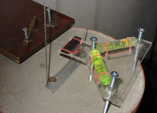
Figure 14 - The assembled microraster holder
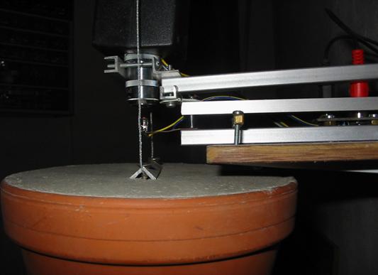
Figure 15 - The assembled device without the microraster holder - side view
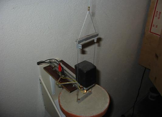
Figure 16 - The assembled device without the microraster holder - top view
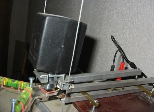
Figure 17 - Fully assembled device - view No.1
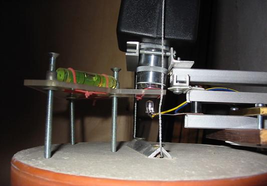
Figure 18 - Fully assembled device - view No.2
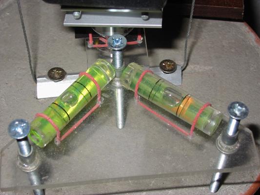
Figure 19 - Fully assembled device - view No.3
Wall fixed variant
The wall fixed variant of the measuring device is used in locality, where there is no useful way of fastening the hanging wire to a ceiling.
The hanging wire is fastened to the wall like to the ceiling and the wire is stretched via support (distance brace) in this case. The support fixes the wire into the right distance from the wall. The support is fastened to the wall. All other parts of the measuring device are the same as in previously described variant.
The schematic description of the wall fixed variant is in the following figure.
Figure 20 - The wall fixed variant of the measuring device
Device parameters
Temperature parameters
The chapter deals with temperature parameters of the measuring device in detail.
Temperature dependent deformations of the microcamera are cylindrically symmetric relative to horizontal axis. Worst case short time temperature differences should be maximally 20°C. Standard material thermal expansion coefficient is less than 10-4/°C. It gives less than 2x10⁻³ relative dimension change i.e. 0.2%. Long term temperature difference is less than 50°C, i.e. less than 0.5% relative dimensions change. It is much less than measurement designed measuring device precision.
Additionally thermal expansion of objective length is compensated by thermal expansion of CCD camera chip.
Thermal expansion of the microraster combined with eccentric position of geometric centre of microraster relatively to the microcamera objective cause temperature dependent microraster position change. If the eccentricity is lower than 5mm (it should be easily fulfilled by measuring device adjusting) and thermal expansion coefficient of microraster holder (plexiglass) is approximately 70x10-6 °C-1 than the position change in eccentricity axis is about 0.35μm/°C.
Thermal expansion of microraster holder causes microraster movement in the holder axis direction dependent on temperature. Active microraster holder length is less than 50mm. Thermal expansion coefficient of plexiglass is typically about 70x10-6 °C-1 (acrylic). Microraster movement is typically lower than 3.5μm/°C.
Movement of the microraster caused by thermal expansion of the weight can be estimated by value about 0.5μm/°C (length is less than 50mm – the same as microraster active length, thermal coefficient of the concrete is about 10x10-6 °C-1 - typical table value are 6x10⁻⁶ -12x10-6 °C-1).
This movement compensates movement of the microraster caused by thermal dependency of microraster holder.
Thermal expansion of the weight does not change mass distribution and the weight centre of the mass position in horizontal plane due to the weight symmetry.
Vertical axis length change of the weight caused by thermal expansion of the weight can be estimated as lower than 2μm/°C. The dimension change causes only the absorber movable ring position change.
The hanging wire thermal expansion causes the weight vertical position change. This movement is about 25μm/°C (thermal coefficient of steel is about 12x10-6 °C-1, wire length is about 2m – it is different in different locality). This movement is compensated by the building movement caused by the thermal expansion of the building. The estimation of the building thermal movement is more complicated. It should be about 12-25μm/°C for concrete building and homogenous heating.
The hanging wire length change has no direct influence to measured deviation. It is orthogonal to the measuring plane. The wire length change affects image focus and image size change. Both effects are symmetric in image area and can affect measurement results only by inhomogeneity of any effect. The serious image inhomogeneity comparable with the image size was not observed.
It was observed serious unfocus effect with time constant many times greater than basic measured deviation period. The unfocus effect with time constant from several days to a few weeks was observed in case of new installation of measuring device in new location. In case of long term continuous measurement in one location focus is stable. It is needed to focus the microcamera in period 3 or more months.
The recommendation is to use measured results after about 10-20 days after begin of measurement in new locality. The result in the beginning of the measurement frequently contains superposition of measurement device ageing movement in new locality. The ageing influences image focus as well.
Focus area for reliable measurement of the real measuring device can be estimated about 50-100μm in vertical direction.
The aluminium microcamera holder thermal expansion is about 4.8μm/°C (length approximately 20cm, aluminium thermal coefficient is about 24x10-6 °C-1).
Total worst case thermal expansion of fully assembled measuring device is approximately 8μm/°C in direction orthogonal to the wall plane.
Real measured thermal expansion was 5.5μm/°C (see appendix A).
Let us compare thermal movement of the measuring device with measured movements.
Main value of measured deviations L2-NS (in L2 locality and North-South direction) with 24 hour period is 20μms-2 i.e. position change amplitude is 4μm. Main value of measured deviations L2-EW (in L2 locality and East-West direction) with 24 hour period is 65μms-2 i.e. position change amplitude is 13μm (the hanging wire length is about 2m).
Main amplitude values different periodic elements of temperature in the L2 locality (internal temperature T-int, external temperature T-ext) and measured deviations in L2 locality are in following table. Absolute values and relative values related to 24hour period value are in the table.
Table 2 – Periodical component amplitudes
The measured main temperature amplitude with period 24hour in the area close to the weight in L2 locality is 0.065°C. It is the greatest periodical internal temperature change.
Let us analyze temperature influence of the measured internal temperature changes to different parts of the measuring device:
- Relative change of the image size is lower than 6.5x10⁻⁷.
- Microraster position change caused by eccentricity is lower than 0.023μm i.e. measurement error is lower than 0.6% of measured deviation main amplitude in NS direction and lower than 0.2% of measured deviation main amplitude in EW direction.
- Hanging wire thermal expansion causes movement with 1.6μm amplitude in vertical direction. The movement has no influence to the measured deviation.
- Microraster position change caused by microraster holder thermal expansion and weight thermal expansion is less than 0.195μm i.e. measurement error is lower than 3.5% of measured deviation main amplitude in NS direction and lower than 1.1% of measured deviation main amplitude in EW direction (with respect of microraster holder orientation NW-SE in L2 locality).
- Microcamera position change caused by microcamera holder thermal expansion is less than 0.312μm i.e. measurement error is lower than 5.5% of measured deviation main amplitude in NS direction and lower than 1.7% of measured deviation main amplitude in EW direction (with respect of microcamera holder orientation NW-SE in L2 locality).
In all cases the error caused by temperature dependency of measuring device different parts in L2 locality is lower than estimated precision of measuring device. The total greatest movement caused by thermal expansion is sum of the microcamera holder movement and the microraster holder movement. It is lower than 9% in the worst case and it is lower than estimated measurement precision.
In other locality with greater temperature change can be measured deviation influenced by thermal dependency in direction of the microcamera holder and microraster holder i.e. in direction orthogonal to the wall plane.
The thermal expansion in direction parallel to the wall plane has several times lower influence value. The value is strongly dependent on errors in the symmetry of measuring device like error in microraster holder orientation caused by the hanging wire torsion change. The total value should be lower than direction orthogonal to the wall due to relation in geometry of measuring device.
The thermal expansion effects influence can by lowered by selection of materials with lower thermal expansion coefficients (like glass). Those materials significantly complicate measuring device fabrication and increase cost. Easier technology and cheaper variant was used.
It is extremely complicated to change materials of the building, where the measuring device is placed. The thermal features of the building should have greater influence to the measured results.
Other effects
Other effects than thermal expansion of measuring device parts can have influence on measured deviation. Those effects were experimentally investigated by black box analysis. Results of the analysis are described in appendix B.
The following text deals with other effects affected by measuring device design.
Electromagnetic effects were minimized by selected material of the weight and mass ratios of the weight and other movable parts of the measuring device. Other design principles minimize electromagnetic effects as well. Both electrostatic and electrodynamics effects were taken into account.
Electrostatic effects are used to be minimized by use of conductive materials (metals) and sometimes combined with additional electrostatic shielding. That design is highly sensitive to time dependent magnetic fields. Time dependent magnetic field induces currents in the conductive material and the current caused magnetic field and force. This inductive effect is frequently used in industry in asynchronous squirrel-cage inductive motor.
Any mechanical part with good conductance and sufficient area where the induced current can circulate causes force interaction in time dependent magnetic field.
Highly effective magnetic shielding is very complicated and very expensive solution for many times smaller devices. In this case is probably impossible to design and manufacture effective magnetic shielding without great change in building construction. That change in building construction practically makes measurement in different localities impossible.
The measuring device design uses materials with medium conductance in parts with dominant mass. No materials with great conductance or insulators with great mass were used. Other parts design minimizes circuits with great area and with great conductance.
Only the hanging wire creates circuit with significant area to create hole for microcamera and microraster. The wire with relative small diameter was selected. Material selection is a compromise between accessibility, mechanical parameters and conductivity.
The weight orientation change together with difference of the microcamera axis from the weight vertical axis can cause errors in measured deviation. The measuring device design minimizes influence of external impacts to the weight orientation change by the symmetry. This effect caused periodic measured deviation can be caused only by the weight material inhomogeneity or by the external field anisotropy. That anisotropy must be significant in space comparable with the weight size.
The weight is made of concrete. The concrete homogeneity can be easily checked during manufacturing.
The torsion change of the hanging wire causes the weight orientation change and errors in measured deviation. The weight orientation change was observed. The greatest orientation change was observed after installation of measuring device in new locality in a few first days of measurement. Measured results contain typical e-kt (logarithmic) shape. No periodicity was observed. The observed effect is explained by aging effects of materials (including torsion change). This effect can be easily numerically eliminated from measured results or can be eliminated by longer period of experiments.
Orientation change of the weight can be caused by thermal expansion of the cable fibre twisting. The real value of coefficient describing the temperature twist effect of the hanging wire is unknown.
The effect causes additional movement of the microraster. It is linear movement orthogonal to the difference between microcamera and the weight axes. The difference value and orientation is strongly dependent on every measuring device adjusting in every locality.
The effect was not recognized in many measurements in one locality with different measuring device adjusting. In case the effect has significant value comparable with measured deviation it must be visible in measured results, namely in compared results from synchronously measured results in very close localities with the very similar temperature conditions and different values and different orientations of the difference between axes.
No such effect was observed (see appendix A).
Aperiodic temperature change is many times greater than periodic temperature change (in L2 locality is aperiodic temperature change more than 100x greater than mean value of 24 hour periodic temperature change). No correlation between long term aperiodic temperature change and measured deviation was observed (see appendix B).
Calibration
Special calibration microraster is used for measuring device calibration. The calibration microraster is displayed on the following figure.
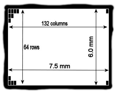
Figure 21 - The calibration microraster
The snapped image of the calibration microraster is used for calibration. The image is snapped by the calibrated measuring device. Example of snapped image is on the following figure.
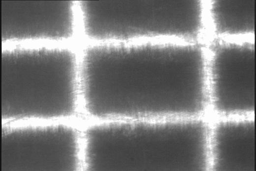
Figure 22 - Microcamera snapped image of the calibration microraster
Calibration constant of the measuring device i.e. size of image pixel is computed from known dimensions of one rectangle (in our case 94μm x 57μm), from full image size in pixel (in our case 768 x 576) and from rectangular image size in pixel (in our case about 390 x 240). In our case is calibration constant about 0.24μm/pixel.
Calibration precision is dependent on the measurement of rectangular image size precision. The rectangular image has unfocused border with different grey levels.
More precision way to measure rectangular image size can be use of digitally filtered image of the calibration microraster.
The digitally filtered snapped image with dimensions used for calibration is on the following figure. Snapped digitally filtered image is one of the backup image outputs of measuring program measure.
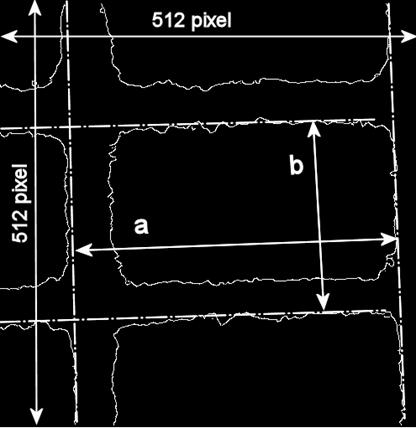
Figure 23 - Digitally filtered image of calibration microraster
Horizontal pixel size is in our case 0.239μm and vertical pixel size is 0.248μm (a = 94μm = 393 pixel, b = 57μm = 230 pixel). The calibration constant of the measuring device is in our case 0.244μm/pixel.
Installation and adjusting procedure
Following text describes the procedure of installation and adjusting of measuring device. The installation and adjusting is divided into steps. Many installation steps include adjusting.
Fasten holes drilling
First step in installing procedure is drilling of fasten holes. Suitable places for the weight holder and the fixed microcamera holder must be selected first.
It is good idea to select flat solid parts of the building. It is possible to select concrete parts or well made brick parts of the building.
It is possible to use wall mounted variant of measuring device in locality with unsuitable ceiling.
It is unsuitable to use parts of the building connected with metal parts of the building skin due to great thermal conductivity or wooden parts or other soft or crumbly parts of the building.
The holes are drilled in selected places and holes are filled by dowels.
It is better to use high quality dowels and screws with diameter in upper part of the dowel range. It enables good connection of the holders with the building construction.
The weight holder fastening
The weight holder is screwed to the ceiling (or to the wall) first. The holding screws should be well tightened.
The fixed microcamera holder fastening
The fixed microcamera holder is screwed to the wall next. The carrying board of fixed microcamera holder should be adjusted into the horizontal plane before screw tightening.
The support should be mounted too if the wall fixed variant is used.
The weight suspending and adjusting
The hanging wire is attached to the weight holder and fixed by lock. The weight must be placed a few millimetres below the fixed microcamera holder and must not be touching with the fixed microcamera holder by any part.
The right vertical position of the weight is adjusted by the lock position on the hanging wire.
It is recommended to set up and adjust absorber as next step.
Mineral oil filled container is placed under the weight. The movable ring vertical position should be adjusted to create about 2-3 mm gap between container bottom and the movable ring. The position of the container should be symmetrical to the movable ring. The movable ring should be immersed into the oil filling of the container but the movable ring must not be touching any part of the container. The absorber will be useful in following adjusting.
The weight orientation adjusting is next step after absorber adjusting.
The weight orientation should be adjusted to enable placement of the microcamera without touching with the hanging wire. The weight orientation is adjusted by the lock turning in the weight holder.
Every change of the lock orientation generates torsion swing of the weight. The swings are attenuated by the absorber. The swings are slow and the weight moment of inertia is relatively great. The adjusting of the weight orientation is time consuming task.
Very high precision symmetry is not needed. Tolerance +/- 15° is suitable precision of adjusting. The adjusting must prevent touching of the hanging wire with any part of the microcamera or the microcamera holder. The ageing of the hanging wire can turn the weight by more than 10° and touching must be prevented in that case.
New hanging wire usually generates the weight turn many times greater than older one. It is recommended to check orientation of the weight more frequently for new measuring device (approximately in period of 15 days) and readjust orientation if needed.
Older measuring device has not that effect. After several months of continuous operation no change in the weight orientation can be observed.
The microcamera fastening and adjusting
The microcamera can be fastened and adjusted after the weight is adjusted. The microcamera is fastened together with the adjustable microcamera holder to the fixed microcamera holder.
The adjustable microcamera holder is fastened by two fixing beams to the carrying board of the fixed microcamera holder.
The adjustable microcamera holder must be adjusted to its right position before tighten of the beam screws.
The microcamera holders design enables compensation of errors in fasten holes placement in range a few cm. It can be very difficult to drill holes into concrete with precision less than a few millimetres. It could be difficult to measure holes position with sufficient precision if the building construction is crooked or uneven. In our case the compensation range is about +/- 1cm in direction parallel to the wall plane and about +/- 2cm in direction orthogonal to the wall plane (both in horizontal plane).
The right position of the microcamera is the vertical axis of microcamera objective should be in the same place as the vertical axis of the weight. The distance between these axes should be as small as possible. No special device was used for adjusting.
The beam screws can be well tightened after adjusting the microcamera. The screws tighten finishes horizontal plane microcamera adjusting. The beams fix the microcamera in the stable position during measurement.
Now we can prepare microcamera to the final vertical position adjusting. The final vertical adjusting will be image focusing. The focus screw placed on adjustable microcamera holder should be set in the centre of focus adjusting range. It means about one half of the distance between upper and lower extreme positions of the focus arm.
The microraster placement and adjusting
The microraster placement and adjusting is the most difficult operation. It is made on the movable weight and it is highly sensitive.
Rough adjusting of the microraster height is the first step. The microraster should be very close to the microcamera objective, but must not touch the objective. The right distance is strongly dependent on objective type. The right distance must enable focusing of the microraster snapped image. In our case the right distance can be estimated in range 0.2-0.5mm from objective lens. In the same step horizontal position of the microraster should be adjusted. The centre of microraster central field (central “page”) should be below the objective centre and microraster holding elastic strips must not touch the objective.
It is not all. In the same step horizontal plane of the microraster holder must be adjusted.
And all these adjustments must be done on the movable weight.
The adjustment needs several manipulations with all three adjusting screws of the microraster holder and placements of the holder on the top of the weight.
It is needed to wait until the weight is calmed and repair wrong adjustment until the position, the height and the horizontal plane is all right.
Good practice is to adjust the central screw first (the microraster holder screw placed nearest to the microcamera) and lately adjust horizontal plane by the other screws separately (every axes of the horizontal plane can be adjusted independently if the adjusting screws create right-angled triangle). Now distances and touching can be checked. If the position is not all right, the step must be repeated.
The last step of the microraster adjusting is inspection. It should be inspected:
- Distance between objective and microraster
- Position of microraster central field
- Microraster holder plane adjusting
- Untouching of elastic strips with objective
- Untouching of microraster holder other parts with microcamera or microcamera holders
- Adjusting of the absorber
It can happen, that during microraster adjusting process the weight moves with great amplitude and pushes the absorber container to the wrong position.
The measuring device mechanical parts installation is finished. The adjusting is very close to the end. Only focusing of the image is needed.
Measurement process
Focusing
Before focusing the computer must be completed, tested and connected to the microcamera.
They are two programs to be used for focusing.
It is possible to use open source program kwintv to display snapped image on the monitor. It can happen, that kwinv was not successfully installed or can not work with used video capture card. In that case it is possible used program snaps and focusing script focus.
Both two programs only displays snapped image on the monitor screen in real time and can be used for focusing the image.
The user point of view difference is that focus script focus snaps and displays the image only 1 time per second. The kwintv uses standard TV speed but used version can not work with all video cards. The kwintv is better if it works.
The focus screw turning changes snapped image focus. If the previous microraster adjusting was all right, it is possible to focus image by the focusing screw. If it is not possible focus the image between upper and lower position of the focus arm, the previous microraster adjusting must be repaired.
It is possible, that the first adjusting will be many times laborious than standard adjusting. It needs experience.
After focusing it is needed to stop all processes working with the camera. The measuring process will need all control of camera exclusively. End the kwintv program or snaps program by the kwintv controls or by kill command.
Now the measuring device is prepared to start measurement.
Initialization
First step of any new measurement after focusing must be initialization. The initialization sets the reference starting position and all measured results are relative to this reference position.
The initialization snaps reference image of the microraster and creates working files.
The initialization should be made if the weight is calmed. It is good idea to wait for calming of the weight movement caused by microraster holder adjusting. The weight is not totally calmed anytime. Small movements can be seen every time if the weight is not touching some fixed part.
The measuring algorithm can work with these small movements and the movements are recorded in the measured output. In case of very great amplitude and “quick” movement like the weight torsion oscillation the measuring algorithm is not able to adapt and follow the movement. The algorithm will start reliable measuring after the amplitude of “quick” movement decreases and result will be with probably random offset. It means, that results will be reliable after decreasing the quick changes amplitudes but the starting reference point will be probable different that the reference used in time of initialization. The worst case is the measurement algorithm will use first auto calibration time. The practical effect is partial loss of measured results (maximally 12 hours) and random offset added to the rest of the result data.
Two files init.txt and init.bmp in /measure/data directory are needed for successful initialization and measurement. It can be used original files or files from previous measurement.
The initialization is started by initobrfiltr script. The script calls measuring program obrfiltr with init parameter –s.
Notes:
- The auto calibration interval is set up by the value intervalc in source code of the obrfiltr9.c. The implicit value is 12 hour and the value can have influence on the total measurement stability. Change of the value can cause unpredictable results.
- The init.bmp file contains information about image size and image file format. If different image size than 768 x 576 is used by video capture card, the file must be replaced and source code of measuring and focusing programs must be changed.
Measurement start
The measuring process can be started after initialization. The initialization must be made before the first measurement start.
The measuring device can start measurement without new initialization in case of restarting measurement in the same adjusting of the mechanical parts. In that case the measurement continues to the previous measurement. That situation can be after PC restart or after power interrupt.
The measurement process is started by measure script. The measure script is executed automatically on PC startup.
The measurement process works with no outputs on the PC monitor as background process.
It can be seen by command ps x.
The actual results can be displayed by command more result.txt or less result.txt in /measure/data directory.
Standard output of obrfiltr program is redirected to /dev/null by measure script.
It is possible to run measurement as foreground process (in case of debugging) and the standard output can be seen on the monitor.
Running inspection
Experience shows good inspection interval about 1 or two weeks. More frequent inspection can change temperature conditions of measuring device or can cause other random mechanical errors. Less frequent inspection increase probability of other errors or problems.
The inspection should check:
- PC disk free space for measured data writing
- Difference of PC clock from the right time
- Image focusing
- Running measurement status
- Measuring device mechanical parts status
PC free disk space can be displayed by df command.
PC time can be displayed by time command and can be adjusted by hwclock command.
Image focus can be tested by displaying of the last backup snapped images by zgv command.
Running measurement status can be checked by displaying process status by ps x command and by displaying last modification time of result.txt file by ls –l command.
Mechanical parts status can be checked visually by observing of the weight, of the microraster holder and water level indicators, of the microcamera position and of the hanging wire position. The observing must be done very carefully to prevent any direct or indirect contact with any part of the measuring device.
In case the inspection shows a need of any readjusting of mechanical parts, the measurement must be stopped. The adjusting can be done and new measurement must be started.
Every touching the mechanical parts creates movements disabling credibility of measured results. New initialization should be done in that case.
Deleting files from PC disk has of course no influence to measured results.
Readjusting PC time should be done if the time difference is greater than 60s. In case of greater errors the result should be backward repaired and time must be recalculated. The time is used only for image sample timing and sample PC time is recorded in results.
Measurement end and connected measurement start
The measurement process can be stopped by kill <measurement process number> command. The measurement process number can be displayed by ps x command.
After stopping the process all result files in /measure/data are prepared for following use and backup.
The data can be copy to another computer for following use by ftp.
The data can be moved for backup in another directory by mv command.
The /measure/data directory must contain only init.txt and init.bmp files before new measurement is initialized and running. Initialization creates new result file.